One of the first things I did with Raspberry Pi was connecting relay board to it and than switch the light, which was connected to the relay, on and off using command line. This wasn’t very useful since every time I wanted to switch light, I had to first SSH to Raspberry and then use the command like “gpio -g write 17 1” to turn on the light. Another problem was that I could only switch two lights because I had to run cables from physical light switch to relays. If I wanted to switch the light that I have on the other side of the room, I would have to install cables through the room. Then I came up with the solution of using few Arduinos + nRF24L01 wireless modules and user friendly web app.
List of parts that I used to make this project:
- Raspberry Pi 2 Model B Project Board – 1GB RAM – 900 MHz Quad-Core CPU
- NRF24L01+ 2.4GHz Wireless Transceiver Module for Arduino
- Arduino UNO R3 Board Module With DIP ATmega328P
- 5V 2-Channel Relay Module For Arduino
- breadboard ($1.5)
- NPN transistor
- 10k Ohm resistors
- 10 uF capacitor
The first problem I encountered was getting arduinos to communicate using nRF24L01 modules. I read on forums that arduino might not provide enough current through 3.3V for powering nRF24L01 modules and I had to solder 10uF capacitor to Vcc and ground pins on the module.
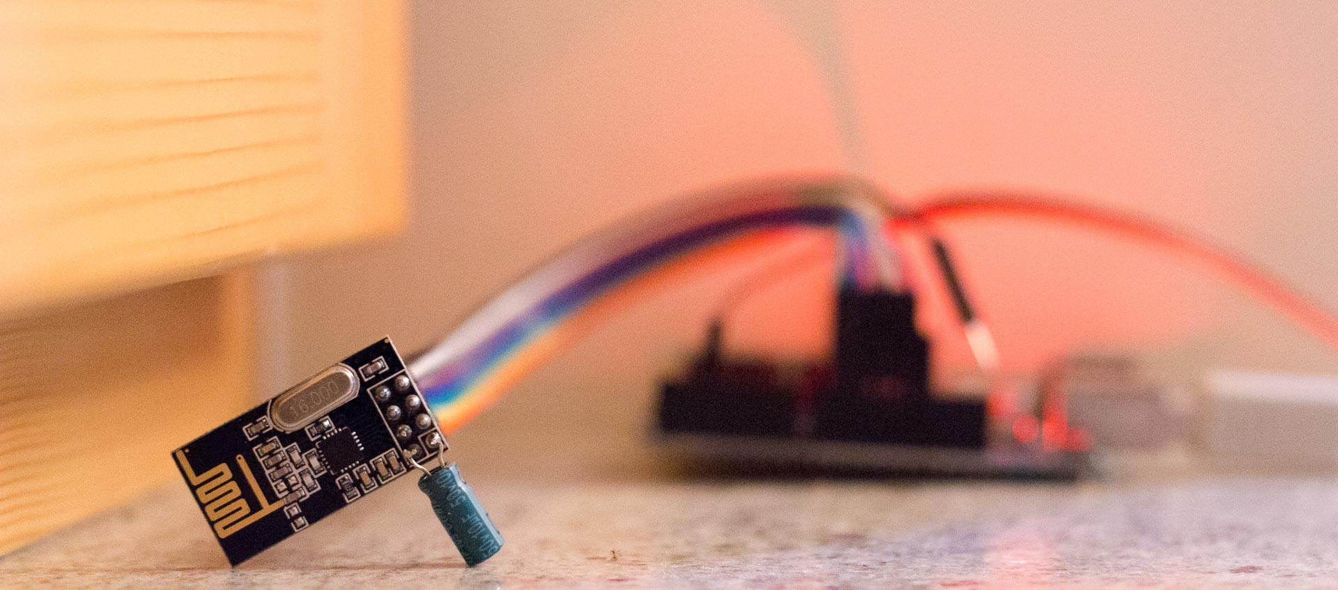
You can check how to connect nRF24L01 module to Arduino here. I used this library for nRF24L01+: RF24 library.
After I got nRF24L01 modules to work, I wrote the arduino program that sends either value 1 or 2 to other Arduino, whenever push button was pressed or released. For the arduino used as receiver I wrote another program that receives data and switches GPIO pin state according to received value. Later I put data in array, so I could control multiple arduinos.
Arduino transmitter – the one connected to raspberry. You only need one.
 #include <SPI.h>
 #include <nRF24L01.h>
 #include <RF24.h>
 #define CE_PIN   9
 #define CSN_PIN 10


 const uint64_t pipe = 0xE8E8F0F0E1LL; // Define the transmit pipe
 RF24 radio(CE_PIN, CSN_PIN); // Create a Radio
 int state[2];
 int i = 5;


 //"button"
 const int buttonPin = 3;
 int buttonState = 0;


 //"button2"
 const int button2Pin = 2;
 int button2State = 0;


 void setup()
 {
    Serial.begin(9600);
   radio.begin();
   radio.openWritingPipe(pipe);

   //"button"
   pinMode(buttonPin, INPUT_PULLUP);

     //"button2"
   pinMode(button2Pin, INPUT_PULLUP);
 }


 void loop()
 {
     buttonState = digitalRead(buttonPin);
     if (!buttonState == HIGH) {
       state[0] = 2;
     }
     else {
       state[0] = 1;
     }

     button2State = digitalRead(button2Pin);
     if (!button2State == HIGH) {
       state[1] = 2;
     }
     else {
       state[1] = 1;
     }

    // radio send on command
        while (i > 1) {
           radio.write( state, sizeof(state));
           i = i - 1;
        }

   i = 5;
 }
Arduino receiver – connected to relay, which is switching the device on/off. You can use more of them.
 #include <SPI.h>
 #include <nRF24L01.h>
 #include <RF24.h>
 #define CE_PIN   9
 #define CSN_PIN 10


 const uint64_t pipe = 0xE8E8F0F0E1LL; // Define the transmit pipe
 RF24 radio(CE_PIN, CSN_PIN); // Create a Radio


 int state[2];
 int i = 1;


 void setup()
 {
   Serial.begin(9600);
   delay(1000);
   radio.begin();
   radio.openReadingPipe(1,pipe);
   radio.startListening();;


   //pins connected to relay module
   //You should use array if you're using more devices
   pinMode(2, OUTPUT);
   pinMode(3, OUTPUT);
   digitalWrite(2, HIGH);
   digitalWrite(3, HIGH);
 }


 void loop()
 {


   //module is constantly listening for data
   if ( radio.available() )
   {
     // Read the data payload until we've received everything
     bool done = false;
     while (!done)
     {
       // Fetch the data payload
       done = radio.read( state, sizeof(state) );


       //if you're using more remote devices, you should use loop
       if ( state[0] == 1 ) {
           digitalWrite(2, HIGH);
       }

       if ( state[0] == 2 ) {
           digitalWrite(2, LOW);
       }

       if ( state[1] == 1 ) {
           digitalWrite(3, HIGH);
       }

       if ( state[1] == 2 ) {
           digitalWrite(3, LOW);
       }

     }
   }
   else
   {
     i = i+1;
   }


   //I experienced some trouble when system was up for a long time and it stopped listening,
   //so in case of a problem, nRF24 module will restart.
   if (i > 50){
     i = 1;
     radio.stopListening();
     radio.begin();
     radio.openReadingPipe(1,pipe);
     radio.startListening();
     delay(1000);


   }


 }
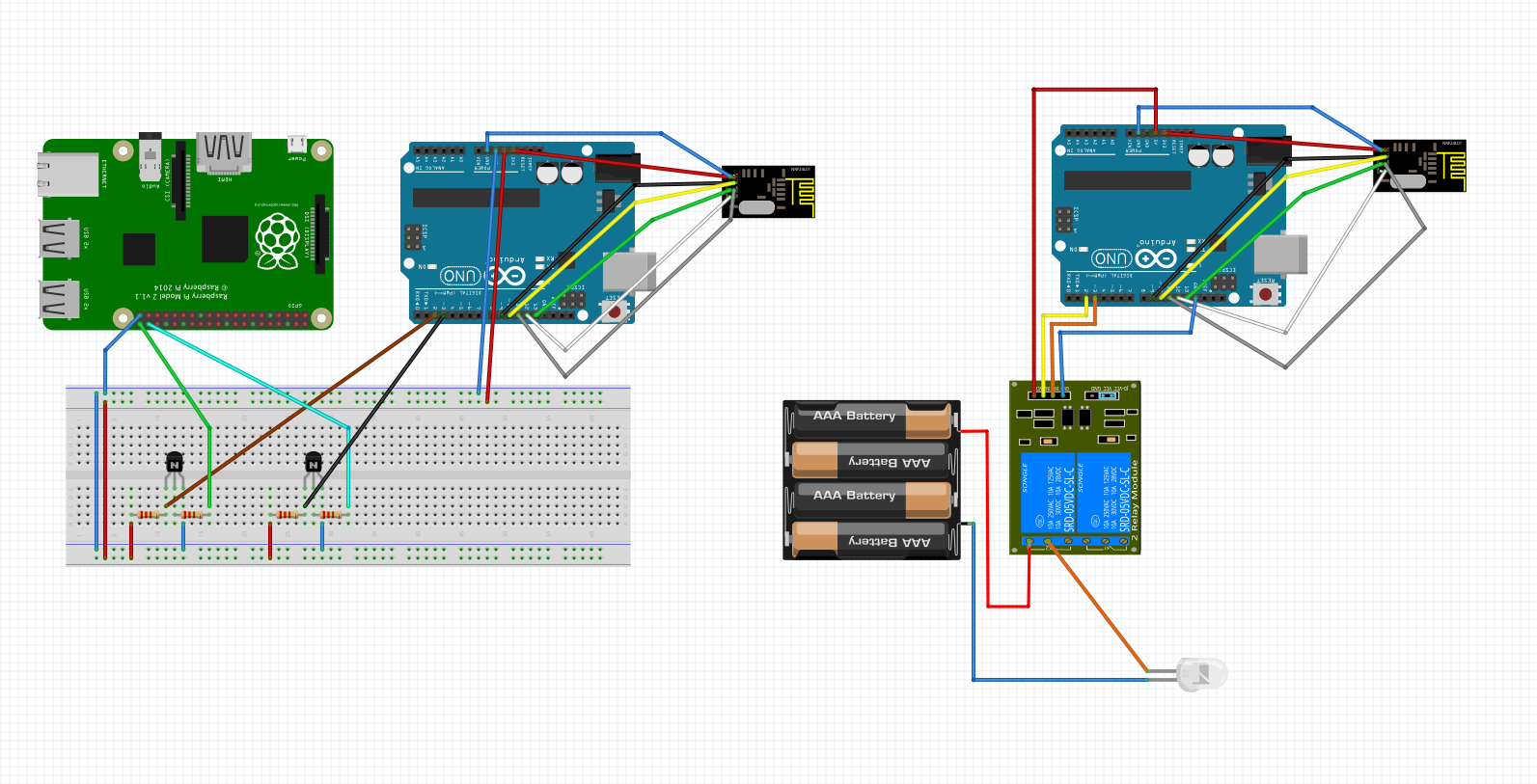
I had to get Raspbery Pi and Arduino-transmitter to comunicate, so I replaced push button with transistor and raspberry pi circuit. Therefore when I used command for changing the GPIO state on raspberry pi – “gpio -g write 17 1”, The current would flow through base of the NPN transistor and hence closing the circuit on the arduino side, so arduino reads different state on gpio pin, causing it to send data to other arduino which controls the light.
Here is my final diagram (both resistors are 10k):
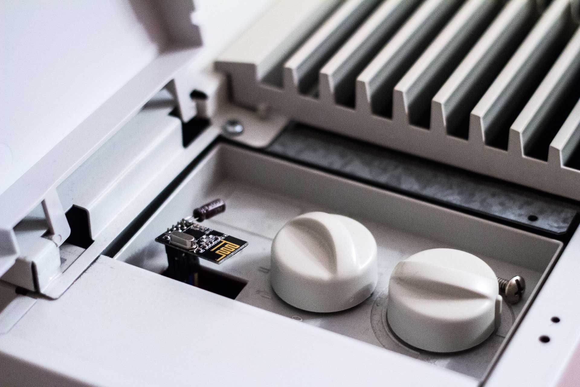
Last step was to make web interface. First I wrote back-end in php for switching GPIO state of one pin on the Raspberry. It executed command to read current state of the GPIO pin and if the state was off, it executed same command as I used before to turn it on and vice versa. So whenever I reloaded the web page, the light turned on or off. I found some jQuerry mobile buttons on w3schools that I later used in my UI. I put gpio pins and names of devices in the array and used foreach loop so when I added another device – air conditioner, I only had to insert GPIO pin and name of the device in the array.
Web app code:
<?php
//specify gpio pins and names for devices
$gpioPins = array(
    17 => 'Big light',
    27 => 'Bedside light',
    21 => 'Small     ',
    20 => 'Air conditioner');

$i = 0;

//check current state for every gpio pin
foreach ($gpioPins as $pin => $name) {
    exec ( "gpio -g read $pin" , $status[$i] );
    $state[$i] = $status[$i][0];
//if button was pressed, change the gpio value of selected device (pin) depending on the previous state
    if ($_POST["$pin"] == "1") {
        system ( "gpio -g mode $pin out" );
        if ($state[$i] == 1) {
            system ("gpio -g write $pin 0");
            $state[$i] = 0;
        }elseif ($state[$i] == 0) {
            system ("gpio -g write $pin 1");
            $state[$i] = 1;
        }
    }
    $i++;
}
/* default gpio state of devices (i'm using pullup like switch for remote devices, so off state is "1")
im using three-way switch for big light, so i can turn on/off light from normal switch too,
but then I can't monitor on/off state of the light using this setup */
$defaultState = array($status[0],0,1,1);
?>
<!DOCTYPE HTML>
<html>
    <head>
        <title>Remote</title>
        <meta name="viewport" content="width=device-width, initial-scale=1">
        <link rel="stylesheet" href="http://code.jquery.com/mobile/1.4.5/jquery.mobile-1.4.5.min.css">
        <script src="http://code.jquery.com/jquery-1.11.3.min.js"></script>
        <script src="http://code.jquery.com/mobile/1.4.5/jquery.mobile-1.4.5.min.js"></script>
        <meta charset="UTF-8">
    </head>
    <body>
        <div data-role="page" id="pageone">
            <?php $i=0; foreach ($gpioPins as $pin => $name) { ?>
            <div data-role="header">
                <h1><?php echo $name; ?></h1>
            </div>
            <div data-role="main" class="ui-content">
                <form  id="test" name="test" action="index.php" method="post">
                    <input type="hidden" name="<?php echo $pin; ?>" value="1"></input>
                    <div class="ui-btn ui-input-btn <?php if($state[$i] == $defaultState[$i]) {print("ui-btn-b");} ?> ">
                        <?php if($state[$i] == $defaultState[$i]) {print("Turn Off");} else {print("Turn On");} ?>
                        <input type="submit" data-corners="false" data-enhanced="true" value="On/Off"></input>
                    </div>
                </form>
            </div>
            <?php $i++; } ?>
        </div>
    </body>
</html>
Video demo:
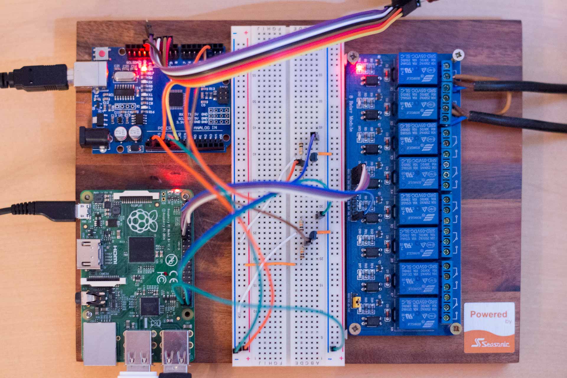
Here is the picture of the final transmitter side setup. I have two GPIO pins on Raspberry connected to relay next to it and two connected to arduino through transistor circuit. Oh, and Aruino is powered by Raspberry pi’s USB.
If you are doing this project yourself, make sure you have installed apache2, php and wiringPi on your Raspberry Pi:
sudo apt-get install apache2 php5
git clone git://git.drogon.net/wiringPi
cd wiringPi
git pull origin
cd wiringPi
./build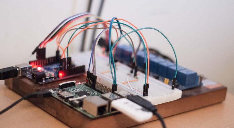


Hello, how you solve problem with your big light… when you turn wall switch off, you can turn on light by phone… You use wall switch for stairs?
Hello, sorry for late answer. Yes, I use a 3 way switch for the big light and I also connected three wires to the relay. But in this case I can’t monitor whenever the big light is on or off.
what transistor you are using in this?
NPN (2N222)
excuse me im pretty new to this rasberry pi stuff but want to control my bed room light with my phone basic stuff to you but i dont understand how to wire the device to my outlet i have a 3 way switch in my room so i think its a benifit i know a bit about electrical i can install 3 way switches so i know the black white and red wires in it i just dont know how to use them wires to connect to the rasberry pi to make it so i can control it anyway you can email me to explane how i would wire it all up in simple turms? my email is chrisrau66@outlook.com i would appreciate it if you could email me about this subject and explan stuff a little better to me thanks
You need Raspberry Pi and relay module. Then, connect ground pin on Raspberry Pi to GDN pin on relay module, 5V to VCC and GPIO17 (or any other gpio pin) to IN1 as shown on this picture: http://i.imgur.com/KGFA1HU.jpg. You can find GPIO pinout for Raspberry pi here: http://i.imgur.com/sTrGZy4.jpg.
For the lights, you would probably need longer wires to connect the ones in your outlet to relays. You need to connect red wire to middle pin on the relay and another two on pins next to it. I would advise you to use a multimeter to test conductivity between pins on the relay in both states (1 and 0).
To switch relay on and off, install wiringPi (instructions in post above) on Raspberry Pi and use this command to set GPIO pin to output and change its state to 1 (3.3V out):
gpio -g mode 17 out
gpio -g write 17 1
To turn it off, use:
gpio -g write 17 0
Commands can be executed in terminal on Raspbian (default OS on Raspbery Pi) or you can connect to Raspberry Pi remotely through SSH.
To find IP address of raspberry pi type: “ifconfig” in terminal. You will also need this IP address to access it from your web browser.
To control lights through website, you need to install apache2 and php on Raspbian, then navigate to /var/www using command “cd /var/www” and create and edit file index.php using command “nano index.php”. Paste code from this post under Web app code and save the file.
Then the website should be accessible using any device on your LAN.
Please let me know if you have any further questions.
thanks so helpful
hello,
thanks for putting this simple and nice example. Have few questions for you, hope to see your reply on them.
1. What is the benefit of using 2 Arduinos + 1 raspi? why not 1raspi and 1 arduino only?
2. How to add more slave arduinos? do I need to define different pipe address for each slave arduino? or use the Array “state” to add for more arduinos?
3. Does each rpi gpio pin required to direct each slave arduino?
4. which software did you use to build the circuit ? it is very nice and I would to use it to build mine
I’m glad you like it:)
1. I couldn’t get library for Raspberry Pi working, so I took this approach.
2. To add more Arduinos, you just need to define new int for each GPIO on Raspberry Pi and Arduino. You also have to wire a transistor between Raspberry Pi and Arduino.
3. Yes
4. You can get the software for making circuit diagrams here: http://fritzing.org/home/
However, I would recommend you to use ESP8266 instead of nRF24L01+ for home automation, since it’s much easier to make and add more slaves. ESP8266 replaces Raspberry pi, Arduino and nRF24L01.
You can read more about it here: https://www.bukovac.si/wemos-d1-arduino-compatible-esp8266/
I have noticed you don’t monetize your page, don’t waste your traffic, you can earn additional bucks every month because you’ve got hi quality content.
If you want to know how to make extra money, search for:
Boorfe’s tips best adsense alternative
It’s a pity you don’t have a donate button! I’d most certainly donate to this outstanding blog!
I guess for now i’ll settle for bookmarking and
adding your RSS feed to my Google account. I look forward to
brand new updates and will share this site with my Facebook group.
Chat soon!
hi!,I really like your writing very a lot! share we
be in contact more approximately your article on AOL? I need
a specialist in this area to unravel my problem.
May be that is you! Having a look forward to see you.
Very impressive. I wish to show thanks to you just for bailing me out of this particular trouble.As a result of checking through the net and meeting techniques that were not productive, I thought my life was done.
Did you know that contact form messages like these are in effect an excellent way to get more visitors and sales for your online or offline business? How exactly do we do this? Super easy, we put together an ad message like this one for your business and we blast it out to thousands contact forms on sites in whatever niche or country you want to target. Do these types of ads work? Of course they do! You’re reading this now aren’t you? The awesome thing is, this doesn’t cost more than $25 a week! Want to get more info? send an email to: UlisesDonaldsoni4472@gmail.com